01 / 30-second recall
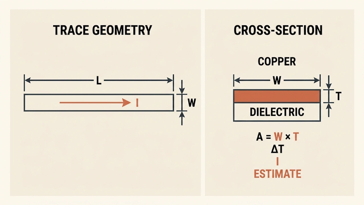
PCB Trace-Width Estimator uses the IPC-2221 empirical model model to connect the entered parameters with a practical engineering quantity. The result is a local estimate, not a measurement.
 51shangTOPSearch
TOOLS / Components
A browser-local PCB Trace-Width Estimator for electronic-information study and early engineering checks.
Quick guide
Input
Output
Knowledge recall
Concepts, relationships, and engineering limits.
01 / 30-second recall
PCB Trace-Width Estimator uses the IPC-2221 empirical model model to connect the entered parameters with a practical engineering quantity. The result is a local estimate, not a measurement.
02 / Core relationship
Use the displayed IPC-2221 empirical model relationship with consistent SI units. Keep the formula, unit conversion, and sign convention together when checking the result.
03 / When to use
Enter the values you actually know, calculate, and then compare the result with the expected range, component limits, and the operating conditions of your design.
Do not treat a nominal value or a first-order model as proof that a real circuit will meet its tolerance, stability, thermal, timing, or signal-integrity requirements.
Use this result for learning and early planning. Confirm the final design with the relevant datasheet, simulation, measurement, layout review, and worst-case conditions.